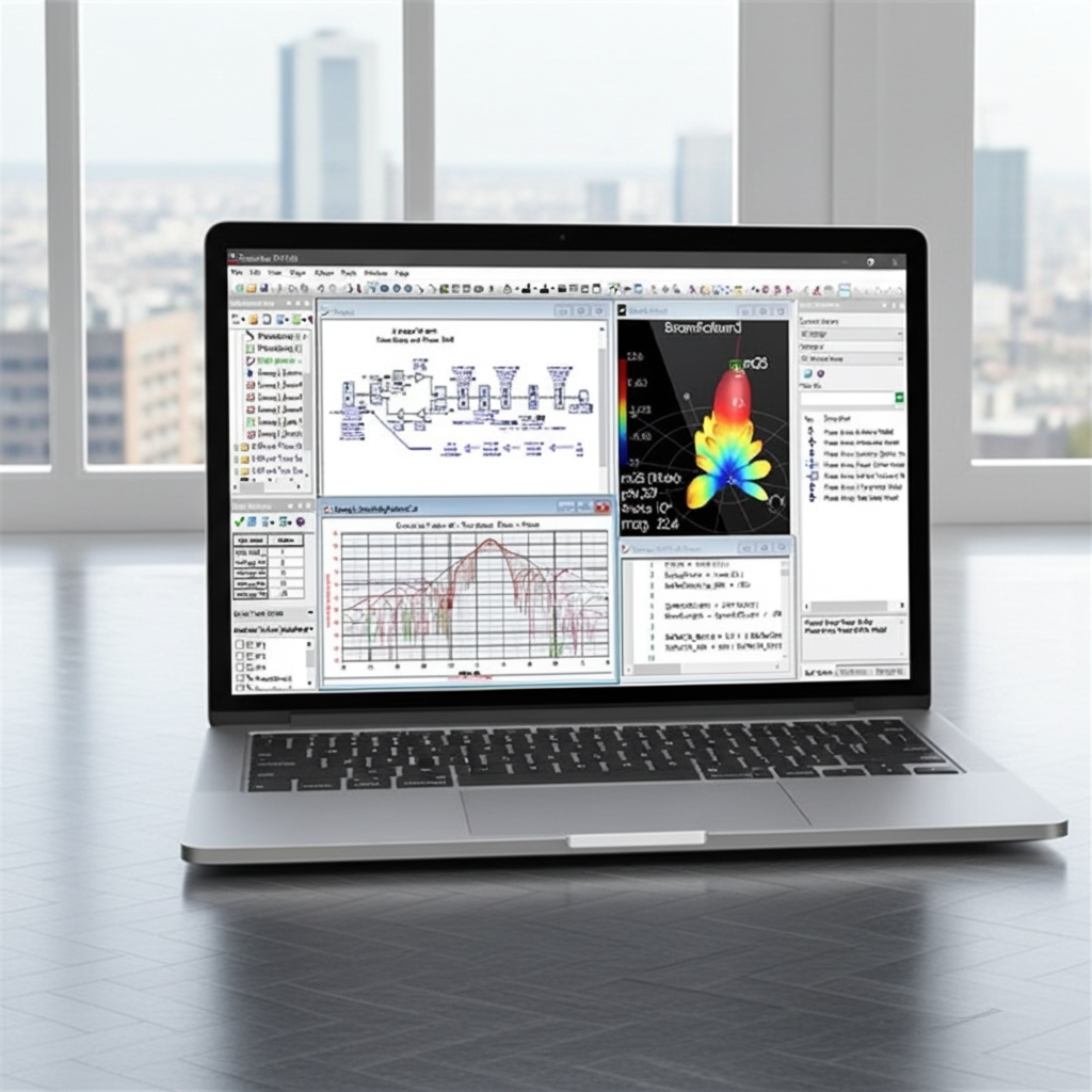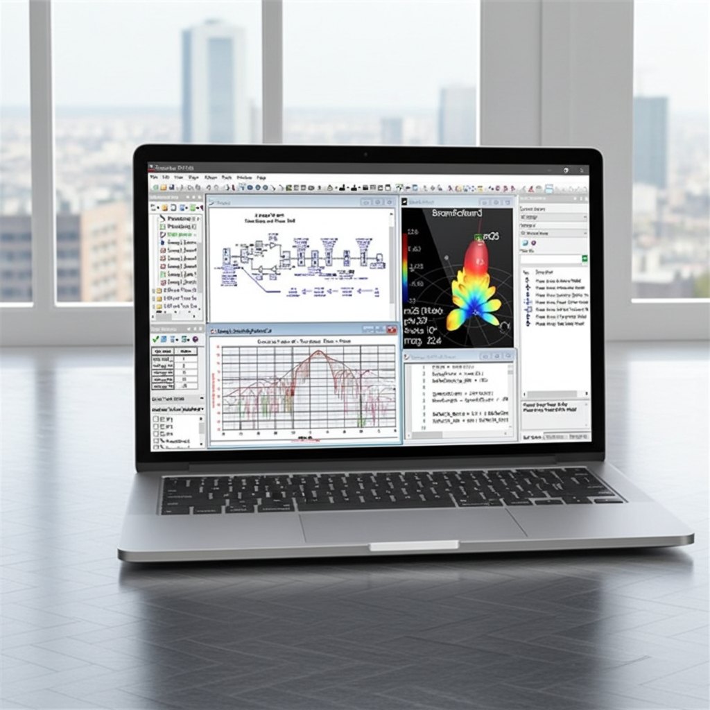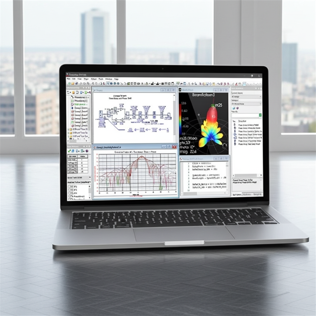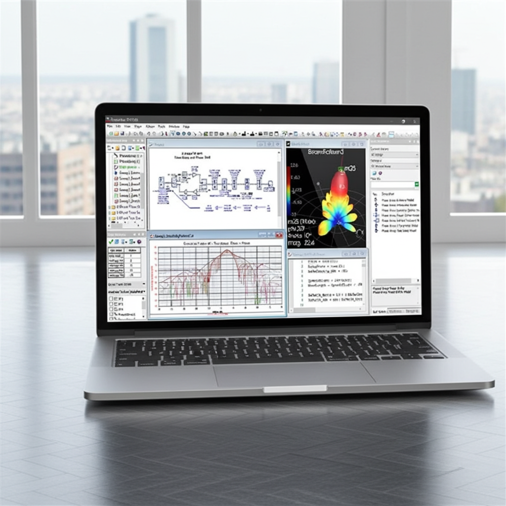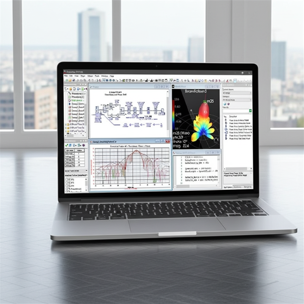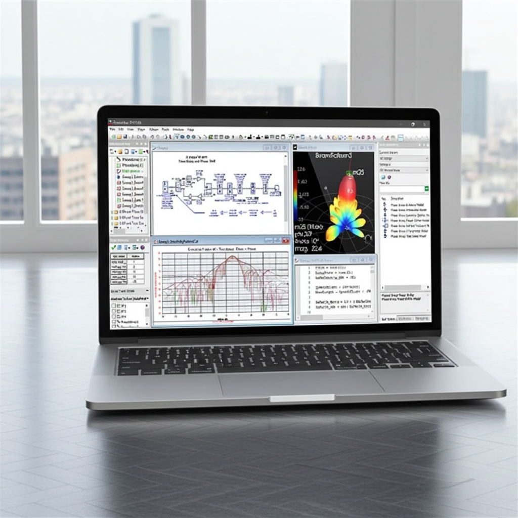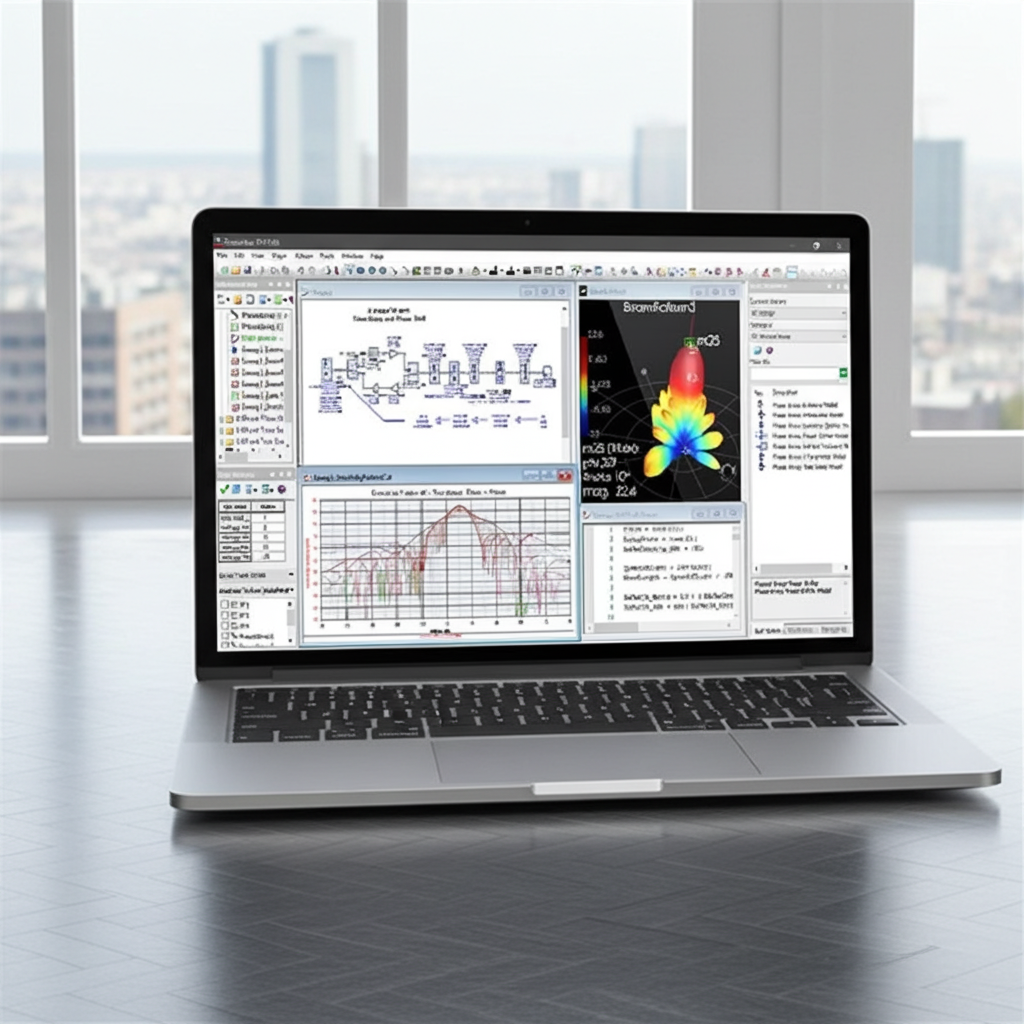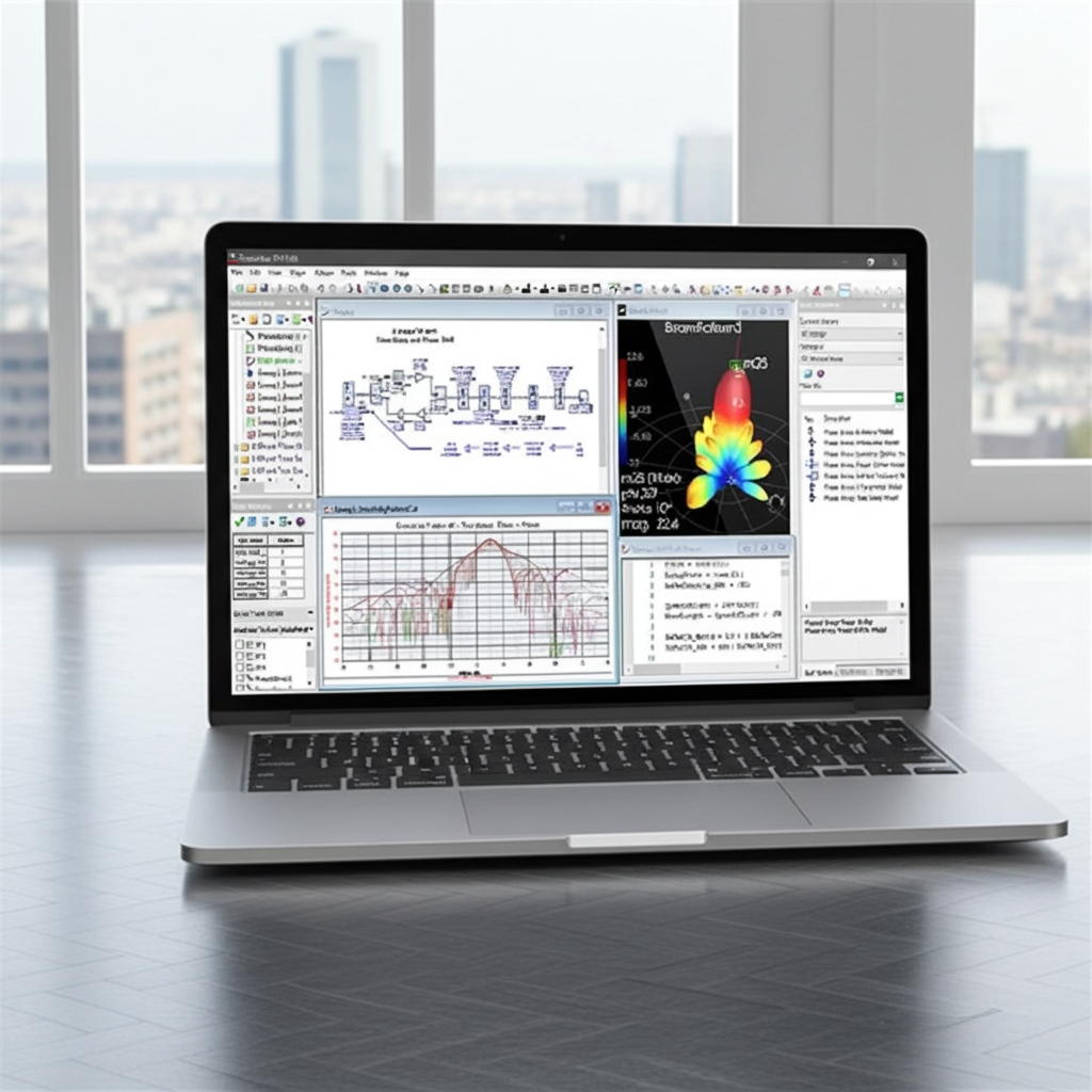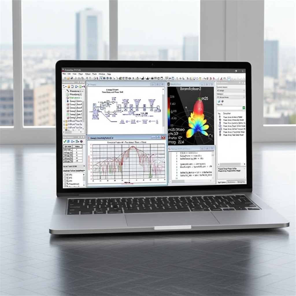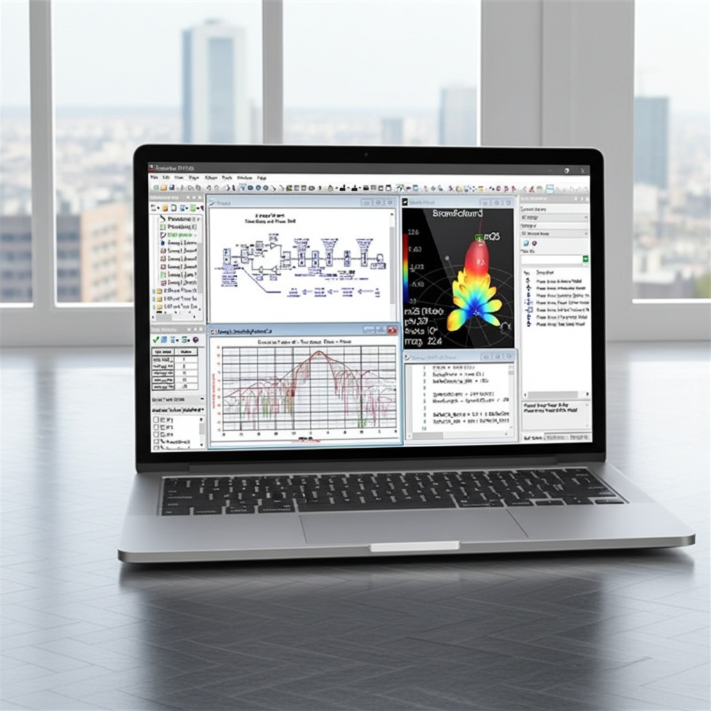
Get Started with SystemVue
For engineers who create DSP circuits and System Architecture designers
Upon completion, you should be familiar with the basics of using SystemVue for digital signal processing and system architecture design. The focus is on the Data Flow simulator for DSP design. The user interface is explained and the analysis setup and plotting of data are practiced through lecture and lab exercises.
- General concepts of system design & User Interface operation
- Data Flow Analysis and Setup
- Post Processing and MATLAB Script
- Graph and data handling
- Tuning Parameters
- Sampled Signals and Data Types
- Building a basic QPSK Tx / Rx System
- Using the Filter Designer
- EVM, BER and other measurements
- RF design using Spectrasys
- Spectrum Plots and Path Level Diagrams
- Models, Sources and Measurements
- Optimization and other Evaluations
- Co-simulating with Data Flow through RF_Link
Phased Array Antenna application design training
- Quickly and easily configure and analyse various phased array systems
- Take advantage of the vast available measurement and statistical evaluations
- Visualize your antenna array in 3D
- Generate 3D beam pattern and 2D cuts
- Model impairments with real antennas, components, and discrete states
- Perform Monte Carlo analyses, and explore antenna polarization
The course combines lecture presentations with guided hands-on lab exercises.
SystemVue Fundamentals
- Overview of SystemVue & workspace structure, basic dataflow analysis and sinks, datasets, graphs and markers, schematics, hot keys, part selector, graph and trace properties
- Toolbars and windows, organizing the workspace, sampled signals and data types, real, complex and envelope signals
- The dataset viewer, sources, timing and sample rate control, modulation models and transmitter design, continuous data plots, the filter designer, parameter sync.
- Receiver Analysis, up and down sampling, hierarchical designs and parameters
RF System Simulation
- RF architecture design and SPARCA, how Spectrasys works, channel and path definitions, level diagrams and spectrum plots and analysis settings.
- S-parameters, X-parameters, MDIF import, frequency dependencies, intermodulation and compression, MultiSource, an amplifier example, sweeps and other evaluations (Optimization, Monte Carlo and Yield).
- Theory of operation, thermal noise, amplifier compression, multiple input and output, control pins, RF-chain with real modulation, the RF_Link component and setup.
Phased Array Antenna Design
- The Phased Array Analysis, how it works and its many measurements. Tx and Rx and comparisons to Spectrasys RF System Analysis.
- The Phased Array Visualizer, different antenna geometries and their properties, tapering, nonlinearities, element patterns and mutual coupling.
- Squinting, Monte Carlo with Errors and Element Failures, harmonic radiation, quantization and polarization.
SystemVue Fundamentals
- Lab 1: Examine templates, use graph properties, edit sinks and insert components, run analyses and view results, tune parameters using sliders.
- Lab 2: Add equations to the workspace using MATLAB script, use the RF modulator, set up of an FM analysis.
- Lab 3: This lab introduces the bit source as the basic source for digital designs, modulated signals, filter designer and other data flow analysis tools.
- Lab 4: Cross correlation, EVM and BER measurements, creating sub-circuit models.
RF System Simulation
- Lab 1: You will create a system schematic, set up a Spectrasys RF system analysis, create power spectrum plots, add a level diagram, extend the system architecture with additional parts and adjust the signal power.
- Lab 2: You will look at FM receiver design issues, improve receiver performance. You will become familiar with intermodulation measurements and optimization of the design for overall system performance.
- Lab 3: Data Flow top level analysis using RF subcircuits.
Phased Array Antenna Design
- Lab 1: You will start with using Spectrasys antenna array, extract the 3D beam pattern, then build the same design using Phased Array parts and compare results.
- Lab 2: You will evaluate how compression, AM-to-PM, saturation and active loading affects the performance of the design. You will be looking at the taper plot, the phi cut directivity graph and the far field 3D pattern. You will load antenna element models and compare them against the isotropic antenna element model.
- Lab 3: You will be using a design consisting of an 8x8 uniform rectangular phased array in receiver mode as a baseline to examine how phase shift and attenuator errors, and element failures, including quantization, affect the array’s performance.
